Custom UI Shaders in HDRP
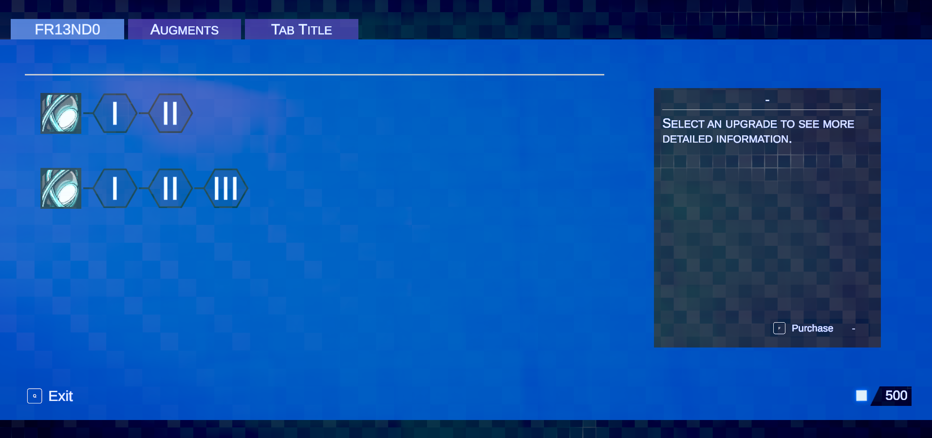
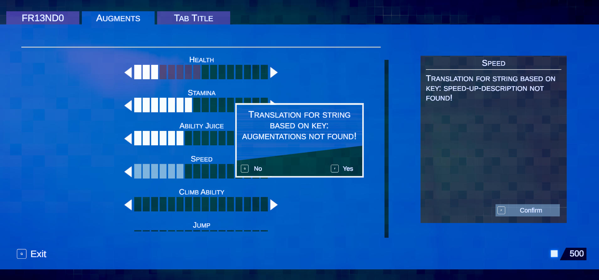
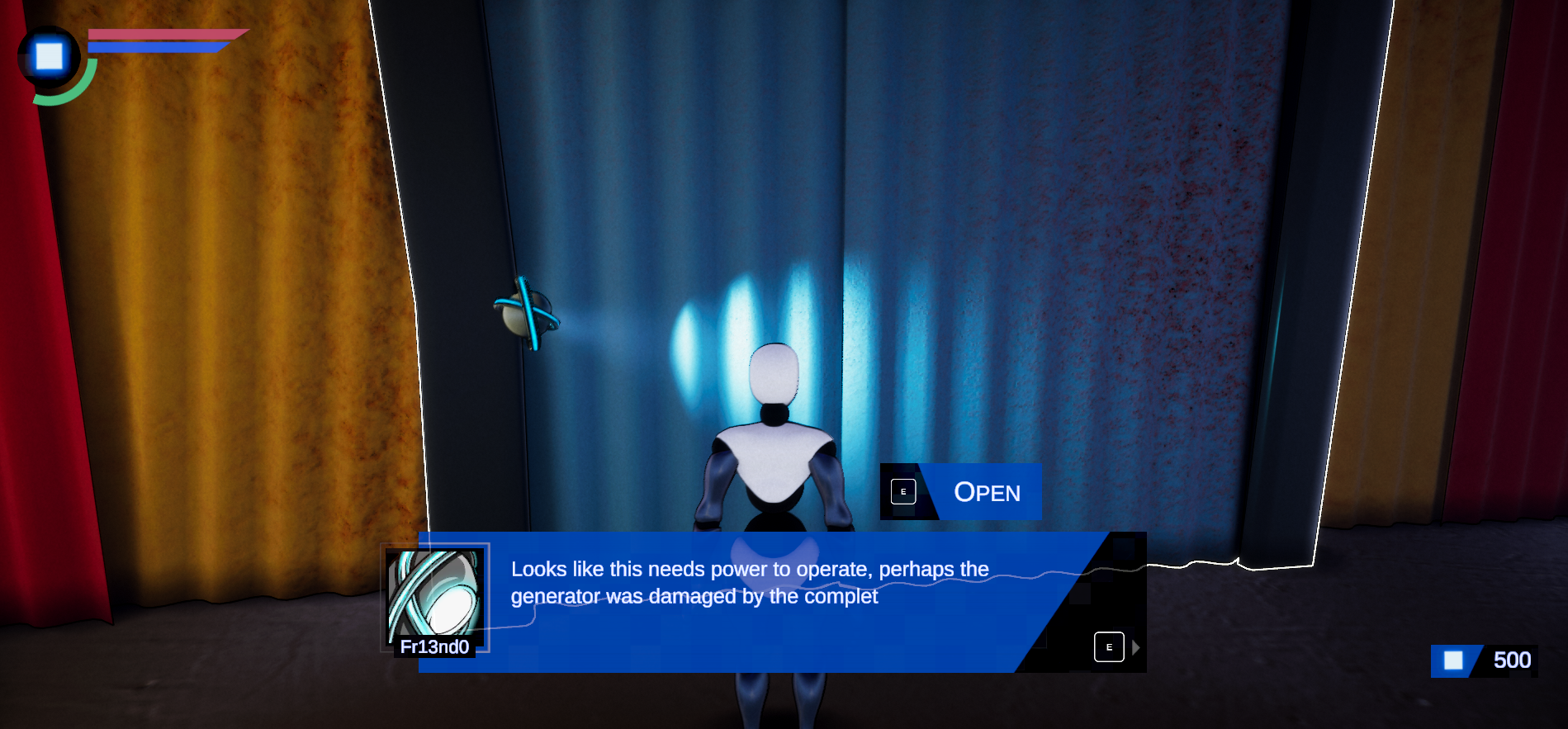
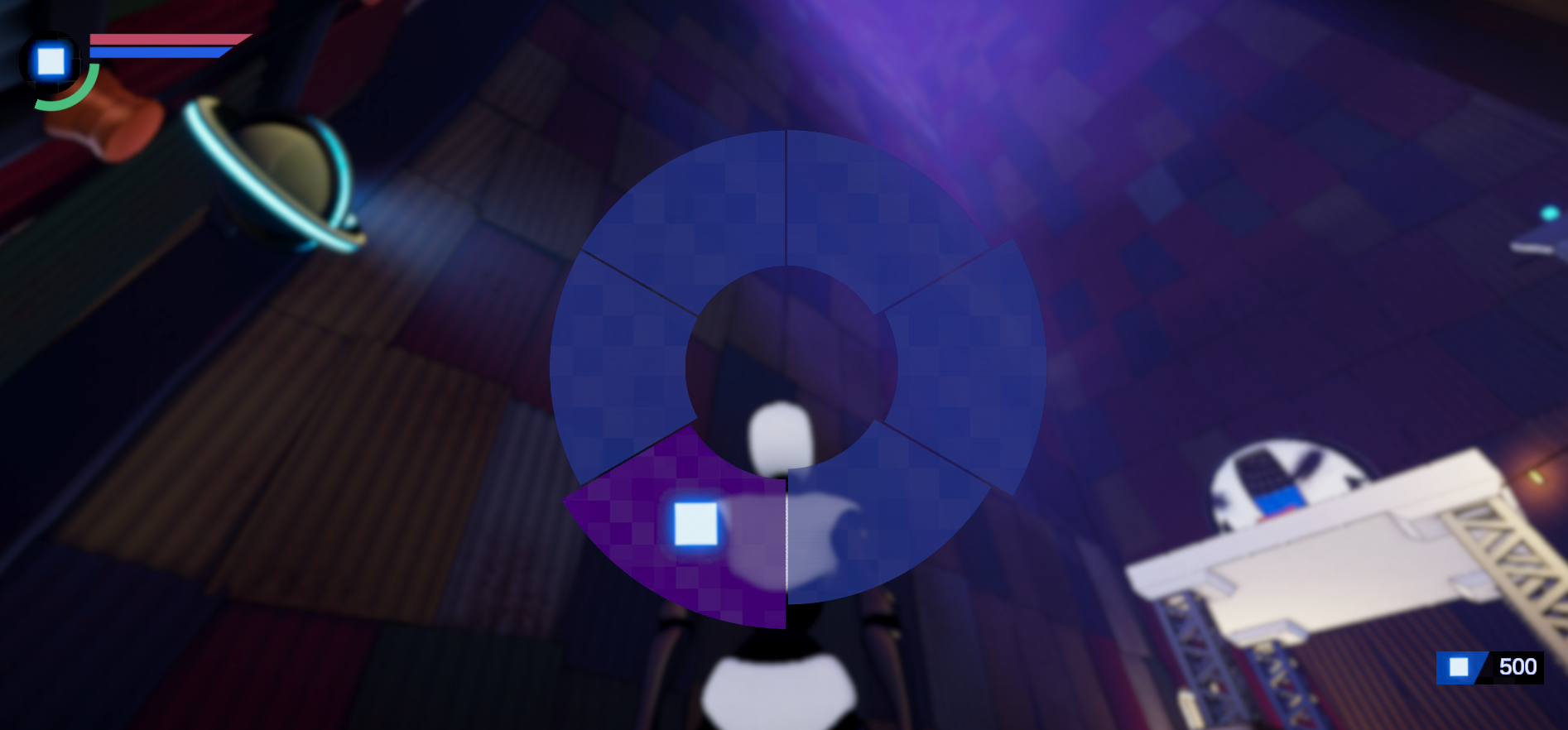
**The Dev log video contains demos of a lot of the work that has been going on, but this write up is going to focus on just the UI and the 3D Map. The gallery below shows the state of the UI work as it stands in more detail.
Standard disclaimer before getting started: All the info here is as it pertains to Unity 2019 LTS using the High Definition Render Pipeline v7.7.1. Yes these are now old versions but this is what I’m locked to for this project. A lot of the details here are still pertinent to more modern versions of Unity and the HDRP, however some things may function differently, better, or worse.
Something I always struggle with in my games is the user interface. My old school developer brain always wants to treat it as “secondary” to the actual mechanics and graphics, but since that is unequivocally a terrible idea I find myself constantly fighting against my urge to slap something “good enough” together and move on. For Project Beta, I really want to put a UI together that is simple but interesting enough to contribute to immersion, rather than looking just bolted on top of everything. I’ve always liked interfaces that leverage interesting shading techniques to either animate or change over time, since it keeps them from looking stale while still generally being simple sprites that are easy to lay out without actual sprite sheets to worry about. Unfortunately, since I’m using Unity and the High Definition Render Pipeline for this project, creating custom UI shaders is somewhat difficult, especially if you’re crazy enough to want to be able to do something so outlandish as to have a scroll area with a rectangular clipping mask, but who could ever imagine such a scenario?
An unnervingly common pattern I’ve noticed with Unity is that if you’re extremely persistent and have spent too much time trying to work around what feels like arbitrary restrictions you can find a way to make most things work even when it seems like they can’t. I figured I’d take some time to document the journey I went on and the workarounds I found to get a reliable and dynamic UI with custom shaders (produced via Shadergraph) working since it was surprisingly difficult and might wind up being useful to other developers.
The first hurdle for this project was trying to figure out the requirements to easily make UI shaders in Shadergraph and have them show up, all other UI interactions aside. If you’ve tried to do this yourself you may have noticed that materials created with a standard Unlit shader don’t seem to show up properly if you have a Canvas set to Screen space - Overlay. My assumption is that this has to do with the coordinate space transforms done in the vertex shader that gets generated from shadergraph (model, view, projection, etc), and the various transforms you have access to as nodes can’t effectively replicate the direct screen space overlay the canvas is doing. If you search for an answer to this problem you’ll pretty quickly find out that if you set your canvas to Screen Space - Camera, you can use a simple Unlit Shadergraph shader for your UI and it will actually show up. Unfortunately, this locks your UI into camera space, which has a few issues. First, if you have post processing you might notice that your UI is also getting post processed (if you’ve ever seen very “bloomy” UI this is likely why.) While this may not sound bad, try using some motion blur and Temporal Anti Aliasing on your UI and then try not to barf. The second problem is that depending on what your materials are doing (specifically depth testing) you’ll find that your UI can actually clip into level geometry.
Like many, many issues in the HDRP the solution to this suite of problems seems to be custom render passes. Specifically, I wound up using a combination of a replacement renderers pass and a full screen “blit” to ultimately draw my UI. For this to work, all of my UI elements are on a specific layer, which is not rendered by my in game cameras. The replacement renderers pass doesn’t replace the materials the UI elements are being rendered with but does override the depth test mode to “always” and executes after post processing. This combination ensures that the UI is drawn on top of everything else and avoids the issues with post processing. Since I wanted the possibility of running my own custom post processing on the UI, I decided to render the UI to an offscreen buffer first, and then use a full screen render pass to draw the buffer back to the camera. This wound up being very handy later on when I was figuring out the shader effects I wanted for Project Beta.
In simple cases, this approach works really well for using Shadergraph shaders in UI. However the elephant in the room for me was always clipping areas. Since there is no direct stencil buffer access in Shadergraph, sprite based clipping masks are somewhat tricky to get working. However, I generally avoid using anything but the Clipping Rect 2D in my Unity projects. The performance detriments of using sprite based clipping are really hard to ignore and I would say that unless absolutely necessary it’s generally best to avoid them. More to the point for Project Beta, however, the only way I could think to properly utilize the stencil buffer was to do what I do for my custom instancing and modify the generated shader code directly. Unfortunately these files are about 9,000 lines long in the version of the HDRP I’m using, so this is really not an appealing option. In the rectangular clipping case, however, things are a bit simpler. As far as I can tell, the rectangular clipping is handled by simple point-in-rectangle tests and modifying the fragment alpha based on the result. The clipping rect(s) seem to be set once per canvas render, and the standard UI material runs the rectangular intersection tests in the fragment shader.
I figured that I might be able to do something similar to this in Shadergraph, at a slight performance cost unfortunately, but it turns out that there really isn’t a good replacement for the ability to mask off UI in areas and I’m not particularly interested in having to write completely custom shaders now that I have tasted the creative freedom of Shadergraph. The basic premise for my custom masking technique is as follows: We can define a clipping rectangle per image, and then convert that rectangle from canvas space to view space. Once in view space, we can send the clipping rectangle definition to each material that needs to be clipped and run an intersection test in view space within Shadergraph. We can then modulate the alpha of each fragment based on whether or not it is inside the clipping area, much the same way the standard 2D rectangular clipping currently works.
There are two main aspects to this approach: the C# side of things and the Shadergraph side, so let’s tackle the C# side first since it’s arguably more difficult to get right. The first step is to create a CustomRectMask2D component and slap it onto whatever we want to clip along with the Unity RectMask2D. It’s worth noting that the RectMask2D isn’t necessary but it does conveniently cull the child transforms when they are entirely out of the clipping area before sending data to the shader and also provides a convenient way to access a defined clipping rect. With this done, the job seems pretty straightforward. We need to access the clipping rectangle defined by the ClippingRect2D, convert that rectangle to view space and then send that definition to each image that needs clipping. Here is a look at what I came up with to accomplish this, there is one big gotcha in here however that I’ll explain below.
protected void UpdateClipping()
{
    // Get the rect mask that contains the definition for clipping
    if (rectMask == null) rectMask = GetComponent<RectMask2D>();
    if (rectMask == null) return;

    // grab the world coordinates of the rect corners that define the clipping area
    Vector3[] worldCorners = new Vector3[4];
    rectMask.rectTransform.GetWorldCorners(worldCorners);

    // Convert the rect transform of the rect mask into view space. Here, cam is a reference to the canvas camera.
    clippingRect = ConvertToViewportSpace(worldCorners, cam);

    // make a 4D vector of clipping values
    clipValues = new Vector4(clippingRect.x, clippingRect.y, clippingRect.x + clippingRect.width, clippingRect.y + clippingRect.height);

    // Grab the Image components that are children of this component. Only do this when the rebuildClippables flag is set to true, since the hierarchy generally won't change.
    if (rebuildClippables)
    {
        clippables = GetComponentsInChildren<Image>(true);
        materialRemapping.Clear();
        foreach (Image image in clippables)
        {
            // build a map of new materials to use for clipping
            if (image.material != null && image.material.HasProperty("_ClippingRect"))
            {
                if (!materialRemapping.ContainsKey(image.material))
                {
                    Material mat = Instantiate(image.material);
                    mat.CopyPropertiesFromMaterial(image.material);
                    mat.SetVector("_ClippingRect", clipValues);

                    materialRemapping.Add(image.material, mat);
                    image.material = mat;
                }
                else
                {
                    image.material = materialRemapping[image.material];
                }
            }
        }
    }
    else
    {
        // send clipping data to the shader
        foreach (Image image in clippables)
        {
            if (image.material != null && image.material.HasProperty("_ClippingRect"))
            {
                image.material.SetVector("_ClippingRect", clipValues);
            }
        }
    }


    updateRect = false;
    rebuildClippables = false;
}


// Helper function to convert an array of 4 corners to View space
public Rect ConvertToViewportSpace(Vector3[] worldCorners, Camera cam)
{
    Vector3[] viewCorners = new Vector3[4];

    for (int i = 0; i < 4; i++)
    {
        viewCorners[i] = cam.WorldToViewportPoint(worldCorners[i]);
    }

    return new Rect(viewCorners[0].x, viewCorners[0].y, viewCorners[2].x - viewCorners[0].x, viewCorners[2].y - viewCorners[0].y);
}
Most of this is pretty straightforward, except for the elephant in the… well code that is the instantiation of a new material instance for each different material our clipped images use. Initially, I thought that UI image materials worked the same way all other materials do, in that you could access a reference to a specific material instance using .material, or a shared material using .sharedMaterial. It turns out this is not the case, since UI draws are really aggressively batched, all Images with the same material reference the same material instance as well, meaning that if you change one shader variable on an image material it changes that variable for all instances of that material as well, including instances on images that you may not want to clipped in this case. The benefit of this for us is that since all the images we want to clip will share the same clipping rect variables we can just set the value once per unique material. The downside is that we have to make sure that each image we want to clip has a cloned version of the base material, so that the images using the same material outside the clipping rect won’t be clipped. This leads to a bit of inefficiency since we wind up effectively doubling the number of materials we are rendering for the UI, but I think the tradeoff is worth it since there doesn’t seem to be any other way to do this.
The last thing we need to do for this custom component isto figure out when we need to rebuild our clippables list. Luckily, if we extend from UIBehaviour we can access a bunch of nifty methods that get called when canvas hierarchy transform changes happen, notably:
OnTransformParentChanged()
OnCanvasHierarchyChanged()
OnRectTransformDimensionsChange()
OnTransformChildrenChanged()
Hooking into these lets us reset our rebuildClippables variable and call UpdateClipping, so that we update our clipping as often as needed but not every frame.
With the C# side sorted, it’s time to take a look at the Shadergraph portion of the UI clipping experience. This is actually pretty straightforward, since we have a clipping rect defined in view space (normalized screen coordinates from (0, 0) to (1,1)). I wound up writing a custom function node for this just because, here is what it looks like:
void UICustomRectMask2D_float(float2 screenPosition, float4 rect, out float Out)
{
    float2 c1 = step(rect.xy, screenPosition.xy);
    float2 c2 = step(screenPosition.xy, rect.zw);
    float2 test = c1 * c2;
    Out = test.x * test.y;
}
If you’re unfamiliar, the step(x,y) function in hlsl just returns 1 if y >= x and 0 otherwise, and can be done component wise. So here we just check the lower left of the clipping rect with the test position and if the test position is greater than the lower left of the clipping rect we return 1. We then make sure the upper right of the test position is less than the extents of the clipping rect. Multiplying the results together will return 0 if we are outside the rectangle and 1 otherwise.
Once we have this set up, hooking the function up to Shadergraph is pretty easy, we just need to make sure to multiply our final alpha value by the result of this clipping test.

Here “RectMask(4)” is the 4D Vector we set from our custom clipping component and has the internal reference of “_ClippingRect.” The output is multiplied by our input texture alpha.
Once I finally got to this point I was pretty pleased to be freely able to use custom Shadergraph shaders for my UI, so naturally I called it a day, happy with my progress and not wanting to push things further.
Ha Ha no, I actually decided to make things much harder by trying to incorporate a fully 3D, auto-generated, orthographically projected interactable map into the UI, because of course I did. Before I immediately jump back into the weeds on this, here is a quick video of the final result:
For Project Beta, the sectors of the city have a very large amount of verticality. In fact there was so much vertical traversal that when I was using a traditional 2D map, I could never figure out where I was, or where I was supposed to be going to get to an objective. I tried adding elevation color coding and even numerical elevation tags to the map markers. This was technically better but required me to somehow “know” what an elevation of 20 meters looks like and resulted in so many overlapping tags that everything just looked like a jumbled mess. This was obviously not ideal. With these issues to overcome, the only real solution to me seemed to be a three dimensional map where you could rotate and zoom freely, easily seeing changes in elevation even in the case of overlapping geometry. Unfortunately, creating an interactive 3D map proved to be somewhat complicated and herein lie the weeds that we are now definitely getting into.
The first problem was generating a 3D model that represented the level geometry. I say generating because I know that manually creating a simplified map is just out of the question for me, especially with how often I iterate on complete level overhauls. The general idea I came up with was to create a MapGeometryProvider class that can be extended from / attached to each mesh that needs to be represented on the map. This component can extract either the lowest LOD mesh or a custom replacement mesh if needed. Since the custom rendering system I’m using already has a component attached to each mesh, it was pretty easy to hook into (the component does get destroyed on play, but as long as we extract the mesh data first this isn’t a problem.) Here is what this extremely simple class looks like:
public class MapGeometryProvider : MonoBehaviour
{
    public Mesh overrideMesh;
    public virtual Mesh GetMapMesh()
    {
        if (overrideMesh != null) return overrideMesh;
        MeshFilter mf = GetComponent<MeshFilter>();
        if (mf != null) return mf.sharedMesh;
        return null;
     }
}
All of the MapGeometryProviders are tracked by a MapGeometryBuilder, which combines all the individual meshes (taking their individual transforms into account) into one while trying to remove redundant vertices, serializes the result and saves a reference to it.
Once this was completed I could push a button and generate a 3D model that was pretty close to a 1 : 1 representation of the lowest detail version of a given level. This was very cool, but unfortunately meant that I had to confront the problem of rendering this model in some sort of interactive UI context without using a second camera (because as I learned long ago, a second camera in the HDRP will absolutely destroy performance.) The clear first step was to render the map geometry in a separate render pass, since it would at least be simple to render it on top of level geometry by disabling depth testing. Once setting this up, there was one glaring issue that I can demonstrate below.


In these cases the map model has actually clipped through the camera, so we are seeing “inside” the map, rather than just looking at the external geometry. This can be very confusing and as the screen shots would indicate, very difficult to visually parse. The classic solution to this problem is to use something called Orthographic Projection for rendering. In an orthographic projection, the “depth” values are effectively contained within the camera’s view, which means there isn’t any geometry clipping. Unfortunately, an Orthographic projection does not have any perspective, which for example would mean that things which are further away from the camera don’t get smaller. This can be sort of confusing as well, however most 3D computer design programs either support or enforce orthographic projection when rendering, because people seem to be able to parse objects without perspective quite well, and understanding the relationships between distances is actually easier than in a Perspective Projection. For this reason, I thought that navigating an orthographically rendered 3D map would probably be the best option. Unfortunately, this is not a particularly straightforward thing to do in Unity. In the days of yore, I would just slap a render texture onto my canvas, stick a second camera in front of my map model and set the projection type to orthographic. However, since Project Beta is using the HDRP, things are not so simple and using a second camera is basically just like setting the computer on fire and walking away.
The first thing I tried was writing a shader that effectively “reversed” the projection matrix on each vertex. This..sort of worked but I could never seem to get the projections quite right, and while this may be a valid solution it annoyed me so much that I don’t think I could really recommend it. What I ultimately wound up doing was writing a custom render pass that was basically just the “Draw Renderers Custom Pass” with one change to the Execute(...) method to set the View, Inverse View, Projection and Inverse Projection matrices of the command buffer to a custom set derived from an orthographic projection matrix. That may sound like some gibberish but this is all it boils down to once inside a custom render pass:
protected override void Execute(ScriptableRenderContext renderContext, CommandBuffer cmd, HDCamera hdCamera, CullingResults cullingResult)
{
    /** Normal boilerplate stuff for DrawCustomRenderers goes here but I left it out because 1. It’s a lot and 2. You can find it all on the Unity github */

    // This is the custom stuff
    Matrix4x4 prevProjectionMatrix = hdCamera.mainViewConstants.projMatrix;
    Matrix4x4 viewMatrix = hdCamera.mainViewConstants.viewMatrix;
    Matrix4x4 prevViewProjectionMatrix = hdCamera.mainViewConstants.viewProjMatrix;

    // GetMapOrthoMatrix is a static function that returns a calculated orthographic projection Matrix based on some parameters the player can change when interacting with it

    Matrix4x4 orthographicProjectionMatrix = GL.GetGPUProjectionMatrix(GameManager.GetMapOrthoMatrix(), true);

    Matrix4x4 viewProjectionMatrix = orthographicProjectionMatrix * viewMatrix;

    cmd.SetGlobalMatrix("_ViewMatrix", viewMatrix);
    cmd.SetGlobalMatrix("_InvViewMatrix", viewMatrix.inverse);

    cmd.SetGlobalMatrix("_ProjMatrix", orthographicProjectionMatrix);
    cmd.SetGlobalMatrix("_InvProjMatrix", orthographicProjectionMatrix.inverse);

    cmd.SetGlobalMatrix("_ViewProjMatrix", viewProjectionMatrix);
    cmd.SetGlobalMatrix("_InvViewProjMatrix", viewProjectionMatrix.inverse);

    HDUtils.DrawRendererList(renderContext, cmd, RendererList.Create(result));

    // Reset what we mucked with
    cmd.SetGlobalMatrix("_ViewMatrix", viewMatrix);
    cmd.SetGlobalMatrix("_InvViewMatrix", viewMatrix.inverse);

    cmd.SetGlobalMatrix("_ProjMatrix", prevProjectionMatrix);
    cmd.SetGlobalMatrix("_InvProjMatrix", prevProjectionMatrix.inverse);

    cmd.SetGlobalMatrix("_ViewProjMatrix", prevViewProjectionMatrix);
    cmd.SetGlobalMatrix("_InvViewProjMatrix", prevViewProjectionMatrix.inverse);
}
Once added as a custom render pass, I could render my 3D map model in a separate orthographic projection! Success! However, I now needed to combine this with a full screen pass in order to get it to render with the UI layer and not in world space and also avoid the classic issues with post processing. A standard full screen custom pass would work for this, but I really wanted to get a nice white outline effect on the map, sort of like old school blueprints. To accomplish this I modified the shader for the custom pass to do some edge detection before blitting the result onto the screen.
The last part of this mess of an undertaking is writing a shader for the actual map geometry. Since I’m invested in it, I decided to do this in Shadergraph, largely for creative freedom. I also wound up implementing a screen space circular clipping mask for the map, so that zooming in didn’t lead to the map encompassing the entire screen. The shadergraph code for the clipping looks like this.

Which just creates an ellipse in screen space and modulates the alpha based on the ellipse. Since I found it helpful when learning about custom render passes, here is what the final pass hierarchy looks like laid out in Unity.

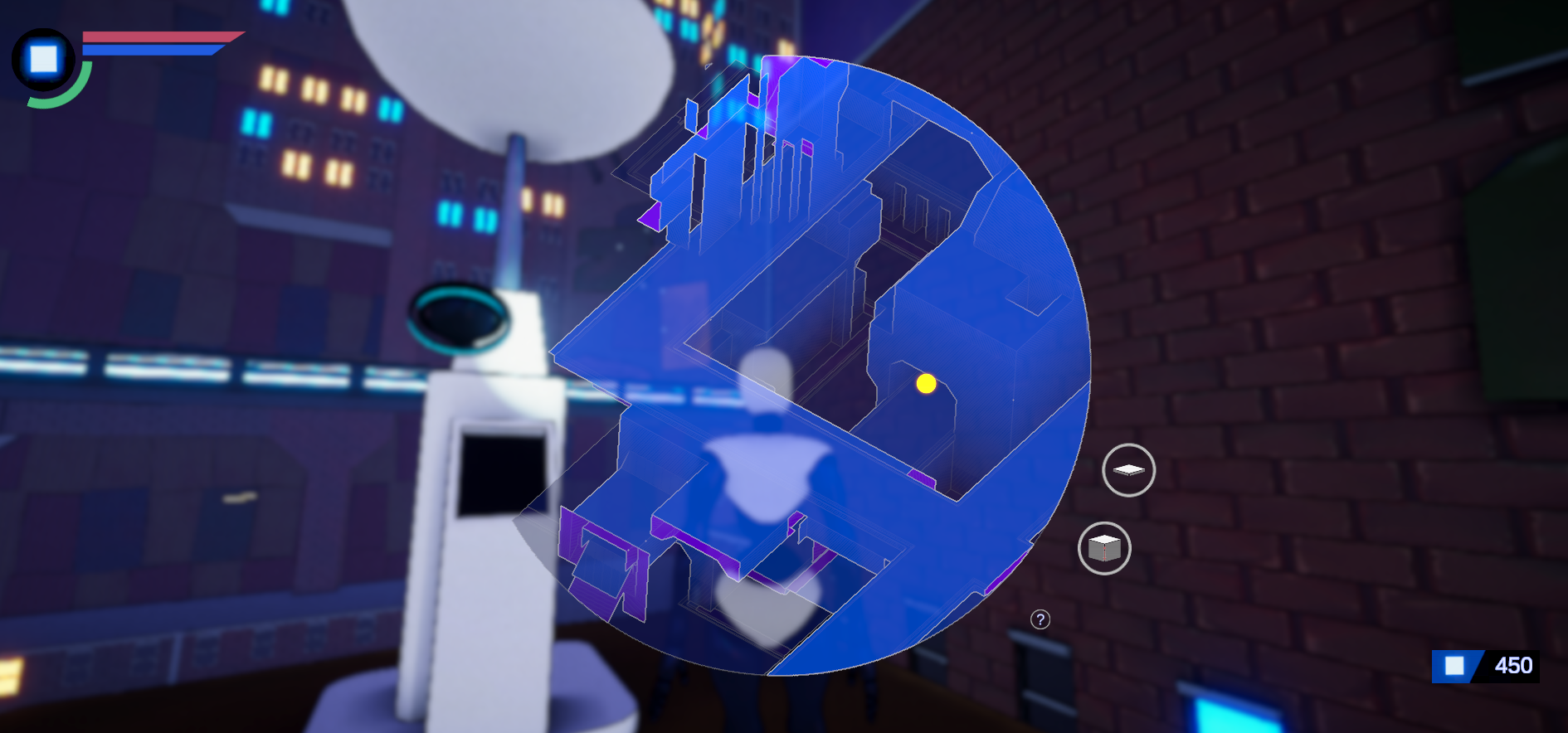
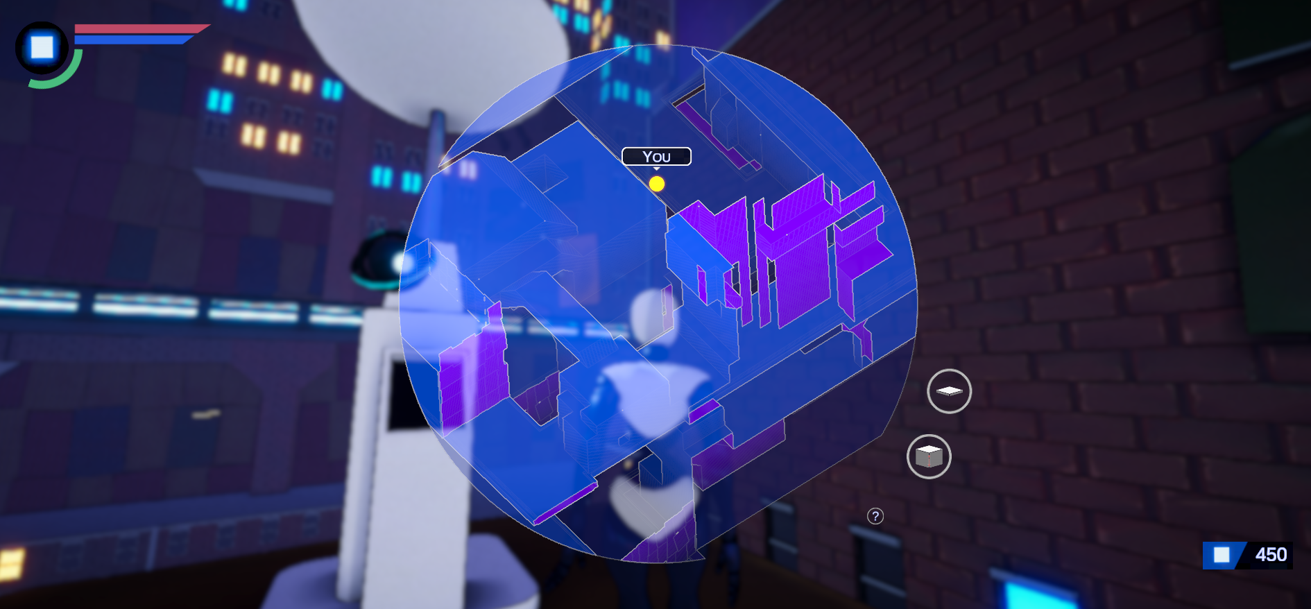
Where “OrthographicPass” is my custom pass that modifies the DrawCustomRenderers pass, and the “Map3D_Blit” material is created from the full screen render pass which runs edge detection and blits the result to the screen. The end result looks like this:

Where the darker colors are lower elevations and the purple represents “back faces” which are usually only encountered on the edges of the map.
After all was said and done, I was ready to call it a day on the map design, until I remembered that it had to actually be usable and therefore needed interactable map markers of some kind. This was quite depressing but is something that happens to me quite a bit when I focus on some technical problem, I sort of lose sight of the point. Anyway, I decided to just get it over with and try to figure out the best way to do this. My first thought was to just put little spheres in the small 3D map, since they wouldn’t suffer from perspective distortion. Unfortunately I soon realized this was dumb since I had to write a tremendous amount of nasty selection code to let you click on something (transforming from screen space mouse positions, back through a custom orthographic projection into “model” space, running some sort of raycast and then choosing the right thing from the hit list.) I realized I wanted the flexibility of real UI components for my map icons, which meant I needed to transform points from world space into map space and then into screen space, taking into account the custom re-projection for the rendering.
This made me sad.
Anyways, skipping over a lot of annoyance and bad ideas, I created a Map3DObject class which handles transformations to keep things where they are supposed to be, the relevant Update loop looks something like this:
void Update()
{
    Matrix4x4 mat = GL.GetGPUProjectionMatrix(GameManager.GetMapOrthoMatrix(), false) * GameManager.cameraManager.mainCamera.worldToCameraMatrix;
    Vector4 targetPoint = new Vector4(target.transform.position.x, target.transform.position.y, target.transform.position.z, 1f);
    Vector4 v = mat * targetPoint;
    v.x =  (v.x / v.w + 1f) * 0.5f;
    v.y = (v.y / v.w + 1f) * 0.5f;

    Vector2 screenPoint = new Vector2(
    ((v.x * canvasRect.sizeDelta.x) - (canvasRect.sizeDelta.x * 0.5f)),
    ((v.y * canvasRect.sizeDelta.y) - (canvasRect.sizeDelta.y * 0.5f)));

	// Some custom clipping code to hide the tags when outside the screen space mask is elided here.

    indicatorRect.anchoredPosition = screenPoint;

}
Where the indicatorRect is the RectTransform of the top level UI element of the GameObject and the canvasRect is the RectTransform of the canvas we are rendering to.
I believe this finally concludes the current UI saga that I’ve been on, hopefully if there are those of you trying to make custom UI shaders in the HDRP some of this will be useful to you. I’m trying out a dev log style more similar to my previous deep tech dives (Procedural Terrain Generation, Procedural Climbing) since I find them more satisfying to write than the more “updatish” style. However, for those curious and following the project, since the last update we’ve finished: AI path planning in 3D, a large art overhaul, the UI system (obviously), basic NPC AI, a dialogue and interaction system, stamina and health systems and an intro cinematic / tutorial. If you prefer this style, or the more “monthly(ish) update” style feel free to let me know in the comments or @UpRoomGames on Twitter.